WebGL Fragment Shader Help
2017-09-16

Contents
1 About Shaders
OpenGL is a widespread method of drawing stuff on a screen. Many apps, games, and other programs use it to do the actual drawing part of what they do. That is, when a program has some object to draw then OpenGL is what is used to actually colour in some pixels on the screen.
In order to do this, OpenGL has to know two things:
-
Where to draw; that is, which pixels on the screen should be coloured in for the given object.
-
What to draw; that is, once we know which pixels should be coloured then we need to figure out the colour.
An OpenGL shader is responsible for doing this, and a shader therefore has two parts:
-
A vertex program which answers the question of where to draw, and
-
a fragment program which answers the question of what to draw.
This website is concerned with the second of these, the fragment program, but to understand that we need to know a little about the first as well.
As the name suggests, the vertex program works by outlining a polygon on the screen by setting its vertices. The polygons used are usually triangles but some versions of OpenGL allow for quadrilaterals as well. As far as this website is concerned, the vertex program sets up a rectangle on the webpage and the fragment program will draw inside this rectangle.
What the vertex program also does is place some data at each vertex of the region. That data is then interpolated into the drawing region and can be used by the fragment program when deciding the colour of a pixel. As a simple example, the vertex program can put a colour at each vertex. Then it is as if that colour spreads out into the rectangle, blending with the colours at the other corners as it goes.
The fragment program then looks at each pixel in turn and decides what colour to put at that pixel. To make that decision, it can use the interpolated information from the vertex program together with other information given to it by the program that started the drawing process.
This website allows you to edit the core part of the fragment program to gain a little experience with what it does.
2 Basic Syntax
The end result of the code that you type into the text box is to set the colour of a pixel on the screen. Colours on computers are usually specified by mixing a certain amount of red, green, and blue. They can then be made partially transparent. In OpenGL, the ranges for these are from to .
Task One: Basic Colours
Replace the code in the box with the following:
lowp vec4 c = vec4(1.0,1.0,1.0,1.0);
gl_FragColor = c;
Click Reload to see what this does.
Some important things to note from this:
-
Every line ends with
; -
The last line will always be of the form
gl_FragColor = ... -
Whole numbers are written as decimals; e.g.,
Try changing the numbers in the first line to see what happens (remember that they must be between and ). You must use a decimal point even if you use or , so write these as and respectively. Vary one number at a time to see its effect.
OpenGL uses four numbers to define a colour, so when working with a colour it wants to link those four numbers together and in a specific order. The word vec4 says “These four numbers should be used to specify a single colour". Writing
lowp vec4 c = vec4(1.0,1.0,1.0,1.0);
says “Use c as a label for a colour, and store in it the colour where each component is set to ".
Task Two: Varying Colours
Replace the code in the box with the following:
lowp vec4 c = vColour;
gl_FragColor = c;
Click Reload to see what this does.
Try changing the corner colours to see their effect (the image should automatically update when these colours are changed).
The special word vColour defines a colour that varies over the rectangle. It is as if a blob of each of the corner colours has been placed at their respective corner and then blended into the rectangle.
Some combinations of colour will result in a definite line from top left to bottom right. This shows that the rectangle is actually made up of two triangles and the blending of the colours is done by the triangles rather than the rectangle.
Task Three: Blending
Replace the code in the box with the following:
lowp vec4 c = vec4(1.0,1.0,1.0,1.0);
gl_FragColor = vColour * c;
In this case, you can vary the numbers in the first line (you need to click Reload when you do) and the corner colours.
What happens here is that we have two colours: a base colour, c, and the varying colour, vColour. We can mix these colours in a variety of ways. The above code multiplies the components of the colours so that the resulting red component is the result of multiplying the red component of the base colour by the red component of the varying colour.
Other ways of combining the colours are:
-
vColour + c -
vColour - c -
vColour / cThis works best when the first three numbers in the base colour are small. Try
vec4(0.1,0.1,0.1,1.0)
There are other, more sophisticated, methods of combining colours which we'll explore in later sections.
Task Four: Colour Swapping
It is possible to access the components of a colour individually or in groups. Replace the code in the box with the following:
lowp vec4 c = vec4(1.0,1.0,1.0,1.0);
c.rgb = vColour.gbr;
gl_FragColor = c;
To see the effect, change the corner colours.
The r, g, and .b refer to the red, green, and blue components of the colours. There's a fourth one, a, which refers to the transparency (known as the alpha). The rules in using them are:
-
The lengths must be the same.
-
There can be repetitions on the right-hand side but not on the left-hand side.
Task Five: Using a Picture
The fragment program can also read information from pictures. In OpenGL, a picture is referred to as a texture. On this website, you can choose textures via the drop down menu and can add or remove textures so that you can use more than one picture.
Replace the code in the text box with the following:
lowp vec4 c = texture2D(texture, vTexcoord);
gl_FragColor = c;
You can choose different images via the menu. The result should update when the image is changed.
There are several new things in this code.
-
texturethis refers to the picture that you've selected in the menu. -
texture2D(...)this looks up a particular point in the picture and returns the colour at that position. -
vTexcoordthis relates the pixel on the screen to its position in the picture.
That last is the key here so let's examine it more closely. To specify a point in the image takes two numbers: and –coordinate and a –coordinate. These are packed together into vTexcoord, in a similar fashion to a colour it is a list of two numbers the first of which is the –coordinate and the second is the –coordinate.
The coordinates are scaled so that the rectangle with the picture in has lower left corner at and upper right corner at .
Task Six: Mixing Colour and Texture
Press Reset so that the text box shows the following:
lowp vec4 c = texture2D(texture, vTexcoord);
c *= vColour;
// Your code in here
gl_FragColor = c;
Click Reload to see what this does.
As before, you can use different operations like += or -= and can use .rgb. You can also use a fixed colour instead of vColour.
Task Seven: Modifying a Picture
Replace the code in the text box with the following:
lowp vec2 t = vTexcoord;
t += vec2(0.5,0.5);
lowp vec4 c = texture2D(texture, t);
gl_FragColor = c;
Just as vec4 refers to a list of four numbers and is used to represent a colour, so vec2 refers to a list of two numbers and is used to represent a position.
The above adds to both the –coordinates and –coordinates of the look-up position. So at a point, say , it actually looks at the colour on the image at . This has the effect of moving the image down and to the left.
What is worth noting here is what happens in the other quadrants. At, say, then the program is looking at . This is outside the picture, so what happens is the gets replaced by and it looks up the colour on the very edge of the picture.
Similarly, a look-up at a negative co-ordinate gets replaced by a look-up on the lower edge of the picture. Later, we'll see how to fix this so that it wraps around.
Task Eight: Zooming In
Replace the code in the text box with the following:
lowp vec2 t = vTexcoord;
t -= vec2(0.5,0.5);
t /= 2.;
t += vec2(0.5,0.5);
lowp vec4 c = texture2D(texture, t);
gl_FragColor = c;
How would you describe the effect of this? Try changing the numbers to see if your description is accurate (make sure that the two occurrences of vec2(0.5,0.5) stay the same as each other).
3 Mathematics
The various things that the fragment program works with all consist of numbers or lists of numbers. Therefore, one can do standard mathematical stuff with them. There are also several functions that prove very useful in fragment programs.
Task Nine: Interpolating Pictures
Click Add texture to get a second texture (which will be called texture1). Choose two different images for the two textures.
Replace the code in the text box with the following, make sure the in the last line has its decimal point:
lowp vec4 c = texture2D(texture, vTexcoord);
lowp vec4 c1 = texture2D(texture1, vTexcoord);
gl_FragColor = mix(c1,c,vTexcoord.x);
There's not a lot to experiment with here. Try changing the images, and you could swap c and c1 in the last line.
Recall that vTexcoord tells the fragment program where the current pixel is in the rectangle. It is a list of two numbers: the –coordinate and the –coordinate.
To get at the numbers individually we can use a variation of the .rgb syntax. The first number, the –coordinate, is vTexcoord.x and the second is vTexcoord.y. So vTexcoord.x tells us how far across the image we are.
The code mix(c1,c,vTexcoord.x) mixes the colours from the two images depending on how far across the image we are. On the left-hand edge, vTexcoord.x is equal to , and mix returns just c1. That is, on the left-hand edge the colour is from texture1. On the right-hand edge, vTexcoord.x is equal to , whereupon it returns just c. That is, on the right-hand edge the colour is from texture.
Half way across, vTexcoord.x is equal to and the mix function mixes the two colours equally. Thus half way along, the colour is a perfect mix of the two pictures.
Task Ten: Smoothly Interpolating Pictures
The above interpolates linearly between the two pictures. Depending on the pictures, the place at which the images are obviously mixing can be quite close to the edges. We can make a slightly more complicated version of the above to concentrate the mixing in the centre.
Make sure you have at least two textures, and replace the code in the text box with the following (as before, watch out for the decimal points):
lowp vec4 c = texture2D(texture, vTexcoord);
lowp vec4 c1 = texture2D(texture1, vTexcoord);
lowp float t = pow(vTexcoord.x,2.0) * (3.0 * vTexcoord.x - 2.0);
gl_FragColor = mix(c1,c,t);
The key here is the formula on the third line. In normal mathematical notation, this is:
The graph of this, for is in Figure 1.
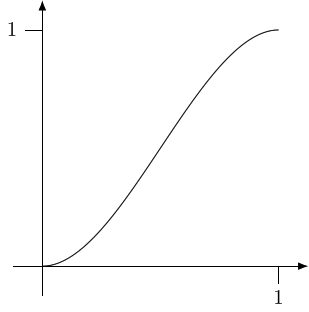
In this code, we've seen how to write powers. The code pow(vTexcoord.x,2.0) squares the value of vTexcoord.x.
Task Eleven: Shifting a Picture
In Task Seven:, we had the following code:
lowp vec2 t = vTexcoord;
t += vec2(0.5,0.5);
lowp vec4 c = texture2D(texture, t);
gl_FragColor = c;
This shifts the picture down and to the left, but the remainder of the picture looks a little odd. The problem is that the program tries to get the colour from the picture at a point that isn't inside the picture. To fix this, we can use the fract function.
lowp vec2 t = vTexcoord;
t += vec2(0.5,0.5);
t = fract(t);
lowp vec4 c = texture2D(texture, t);
gl_FragColor = c;
The fract function throws away the whole number part of a number, leaving just the decimal part.
Other useful functions for changing the texture coordinates (and colours) are:
abs |
the absolute value of a number: | |
min |
the minimum of some numbers: | |
max |
the maximum of some numbers: |
Another useful function is clamp. This is used to clamp one number between two others. For example, will always return a number that is between and . If is between and then it will return , but if is below it will return and if is above it will return .
Try the following:
lowp vec2 t = vTexcoord;
t -= vec2(0.5,0.5);
t = abs(t);
lowp vec4 c = texture2D(texture, t);
gl_FragColor = c;
lowp vec2 t = vTexcoord;
t = min(vec2(0.9,0.9),t);
lowp vec4 c = texture2D(texture, t);
gl_FragColor = c;
lowp vec2 t = vTexcoord;
t = max(vec2(0.1,0.1),t);
lowp vec4 c = texture2D(texture, t);
gl_FragColor = c;
lowp vec2 t = vTexcoord;
t = clamp(t,vec2(0.1,0.1),vec2(0.9,0.9));
lowp vec4 c = texture2D(texture, t);
gl_FragColor = c;
4 Advanced Mixing
In Section 3 we saw some ways to mix two pictures. In this section, we'll see some more that offer more control.
Task Twelve: Masks
With two pictures, one way to decide how to mix them is to use a mask. This acts like the tape that painters put down to protect some areas when decorating: the places where the tape was show the original colour and where it wasn't shows the new colour.
Using a mask requires three pictures: the two pictures to be mixed and the mask. There are various masks built in, to see what they look like use the following code and select a mask as the main texture.
lowp vec4 c = texture2D(texture, vTexcoord);
gl_FragColor = c;
To use a mask to select between two pictures, we use the interpolation formula as explained in Task Ten: but with the mask colour instead of the texture coordinates.
With the following code, the two pictures are texture and texture1 while the mask is texture2.
lowp vec4 c = texture2D(texture, vTexcoord);
lowp vec4 c1 = texture2D(texture1, vTexcoord);
lowp vec4 m = texture2D(texture2, vTexcoord);
c = mix(c1,c,m);
gl_FragColor = c;
A standard extension is to include grey in the mask to indicate partial masking.
Task Thirteen: Alpha Masks
With some pictures, the part that you want masked is (almost) always going to be the same. For these pictures it is possible to add the mask to the picture by making parts of it transparent. This is done using the alpha channel. Recall that OpenGL uses four numbers to specify a colour. Three of these are the red, green, and blue components of that colour. The fourth is the alpha component which specifies the transparency. This can be used in place of a mask.
The silhouettes and characters are good ones to use for the second texture with this.
lowp vec4 c = texture2D(texture, vTexcoord);
lowp vec4 c1 = texture2D(texture1, vTexcoord);
c.rgb = mix(c.rgb,c1.rgb,c1.a);
gl_FragColor = c;
If you try this with one of the characters, the result might look a little odd in that the character is distorted. This is because the second texture is stretched to fit the same size as the first. We can correct for this because the program tells the shader how big each image is: width and height are for the initial texture, then width1 and height1 for the texture texture1 and so on.
lowp vec4 c = texture2D(texture, vTexcoord);
lowp vec2 t = vTexcoord;
t.x *= width/width1;
t.y *= height/height1;
lowp vec4 c1 = texture2D(texture1, t);
c.rgb = mix(c.rgb,c1.rgb,c1.a);
gl_FragColor = c;
Now we might decide that the character is too small and in the wrong place. We can move it around by adjusting the t variable. It's probably easiest to think of moving the character relative to the background so we move it before adjusting the size. Recall that the texture coordinates are scaled so that the background image is one unit across and one unit up.
lowp vec4 c = texture2D(texture, vTexcoord);
lowp vec2 t = vTexcoord;
t -= vec2(0.5,0.5);
t /= 5.0;
t.x *= width/width1;
t.y *= height/height1;
lowp vec4 c1 = texture2D(texture1, t);
c.rgb = mix(c.rgb,c1.rgb,c1.a);
gl_FragColor = c;
Notice that to make the character bigger then we divide the texture coordinates by the scale factor, and to move it to a coordinate then we subtract the amount we want to translate it by. Depending on the background that you use and the characters, you may need to adjust the scale.
Adding more characters is simply a matter of repeating the relevant code (in a full shader editor, you could define a function to do this and simply call that, but this system doesn't allow you that much control).
lowp vec4 c = texture2D(texture, vTexcoord);
lowp vec2 t = vTexcoord;
t -= vec2(0.5,0.1);
t /= 2.0;
t.x *= width/width1;
t.y *= height/height1;
lowp vec4 c1 = texture2D(texture1, t);
c.rgb = mix(c.rgb,c1.rgb,c1.a);
lowp vec2 t2 = vTexcoord;
t2 -= vec2(0.6,0.1);
t2 /= 2.0;
t2.x *= width/width2;
t2.y *= height/height2;
lowp vec4 c2 = texture2D(texture2, t2);
c.rgb = mix(c.rgb,c2.rgb,c2.a);
gl_FragColor = c;
5 Further Experiments
We've only scratched the surface of what's possible with shaders, even with this restricted situation. Here are some more to play with.
Task Fourteen: Squaring
If you know about complex numbers, this one does .
lowp vec2 t = (vTexcoord - vec2(0.5,0.5))*2.0;
lowp vec2 tx;
tx.x = t.x * t.x - t.y * t.y;
tx.y = 2.0 * t.x * t.y;
tx /= 2.0;
tx += 0.5;
lowp vec4 c = texture2D(texture, tx);
gl_FragColor = c;
If you liked that one, try this:
lowp vec2 t = (vTexcoord - vec2(0.5,0.5))*2.0;
lowp vec2 tx;
tx.x = t.x * t.x * t.x - 3.0 * t.x * t.y * t.y;
tx.y = 3.0 * t.x * t.x * t.y - t.y * t.y * t.y;
tx /= 2.0;
tx += 0.5;
lowp vec4 c = texture2D(texture, tx);
gl_FragColor = c;
Task Fifteen: Droste
The Droste effect is where an image gets copied into itself. This is quite straightforward with shaders.
First, a circular one.
lowp vec2 t = (vTexcoord - vec2(0.5,0.5))*2.0;
t.x *= width/height;
lowp float r = length(t);
t /= r;
r = pow(2.0,-fract(-log2(r)));
t *= r;
t.x /= width/height;
t /= 2.0;
t += vec2(0.5,0.5);
lowp vec4 c = texture2D(texture, t);
gl_FragColor = c;
To make it elliptical, with the aspect ratio of the picture, comment out the lines with width/height in them. To change the focus, change the vec2(0.5,0.5) to something like vec2(0.3,0.6) both in the first line and near the end.
Next, square.
lowp vec2 t = (vTexcoord - vec2(0.5,0.5))*2.0;
t.x *= width/height;
lowp float r = max(abs(t.x), abs(t.y));
t /= r;
r = pow(2.0,-fract(-log2(r)));
t *= r;
t.x /= width/height;
t /= 2.0;
t += vec2(0.5,0.5);
lowp vec4 c = texture2D(texture, t);
gl_FragColor = c;
Or we could have a diamond.
lowp vec2 t = (vTexcoord - vec2(0.5,0.5))*2.0;
t.x *= width/height;
lowp float r = abs(t.x) + abs(t.y);
t /= r;
r = pow(2.0,-fract(-log2(r)));
t *= r;
t.x /= width/height;
t /= 2.0;
t += vec2(0.5,0.5);
lowp vec4 c = texture2D(texture, t);
gl_FragColor = c;
Task Sixteen: Escher
If you like the Droste effect, here's an Escherian spin on them.
lowp vec2 t = (vTexcoord - vec2(0.5,0.5))*2.0;
t.x *= width/height;
lowp float r = length(t);
lowp float th = atan(t.y,t.x)/6.28318530718;
t /= r;
r = pow(2.0,-fract(-log2(r) + th));
t *= r;
t.x /= width/height;
t /= 2.0;
t += vec2(0.5,0.5);
lowp vec4 c = texture2D(texture, t);
gl_FragColor = c;
Now with squares.
lowp vec2 t = (vTexcoord - vec2(0.5,0.5))*2.0;
t.x *= width/height;
lowp float r = max(abs(t.x),abs(t.y));
lowp float th = atan(t.y,t.x)/6.28318530718;
t /= r;
r = pow(2.0,-fract(-log2(r) + th));
t *= r;
t.x /= width/height;
t /= 2.0;
t += 0.5;
lowp vec4 c = texture2D(texture, t);
gl_FragColor = c;
And finally, with diamonds.
lowp vec2 t = (vTexcoord - vec2(0.5,0.5))*2.0;
t.x *= width/height;
lowp float r = abs(t.x) + abs(t.y);
lowp float th = atan(t.y,t.x)/6.28318530718;
t /= r;
r = pow(2.0,-fract(-log2(r) + th));
t *= r;
t.x /= width/height;
t /= 2.0;
t += 0.5;
lowp vec4 c = texture2D(texture, t);
gl_FragColor = c;
6 Some Technical Details